Forum Replies Created
-
AuthorPosts
-
 RichCarterParticipant
As for the main cabin companionway issue, leaks there are a problem. Pearson used silicone sealant to bed the teak hatch frame. This is the wrong stuff to use. Here’s what I did.
http://www.richardcarter.net/boat/deckRot/This gets rid of the rotted balsa and seals the hatch frame from further leaks but it doesn’t remove moisture trapped in the deck. I did an exhaustive web search to see if I could find a thread that discusses drilling a pattern of holes on the underside of the deck to allow damp balsa to dry; no luck. If it works, it would be a simple and harmless way to get the moisture out. Getting the coach liner down and back up will be a PIA. Velcro tape holds the panels in place and the adhesive is shot. I plan to add wider teak strips over what’s there to hold the liner panels and ditch the velcro.
My moisture meter shows no moisture around most of the cabin attachments. Leaks under grab-rails are a common problem in older boats but the meter shows no intrusion in my boat. I plan to use the meter on a periodic basis to find any new leaks but I don’t plan to start removing hardware that isn’t showing signs of leakage.
Rich
RichCarterParticipantA friend of mine is trying to sell his Endeavour 40 and has run into problems because his deck has moisture in it. A survey showed moisture on his moisture meter and a prospective buyer backed out because his lender wouldn’t approve the loan on that basis. This got me thinking about my deck. My decks are solid but I think I may have moisture in some limited areas. I’ll be selling my boat someday and don’t want to have problems like he has.
I purchased a non-contact Ryobi E49MM01 pinless moisture meter and ran it across my deck. At $40, it seemed worth risking that it would work on fiberglass. It appears to work well though I don’t know how accurate it is. Most of the deck shows zero moisture but I found several areas that register over 10%. Small areas around a few stanchions, the deck around the maincabin companionway hatch, and the bow area forward of the anchor locker under the windlass register as wet. This is expected. The stanchions and hatch are already repaired. The bow area will be later repaired. The deck area forward of my mast registers as much as 15% moisture. I have a cabin heater that vents through the deck and is likely the cause of this moisture though it may have entered from the mast collar as well.
Yesterday, I pulled the chimney cap from the heater and examined the deck core. The chimney is about four inches in diameter and the hole a bit bigger. There is a small bit of rot around part of the hole. I removed perhaps an inch or two of soft balsa using hex wrenches on a drill. I filled the exposed deck with thickened epoxy and replaced the heater cap. There is no way for water to enter around this hole now.
As I said above, there is no sign of delamination but I’d like to get the moisture out of my deck. I’m planning to access the underside of the deck and will drill a pattern of holes in the wet areas through the underside. I expect the core will dry over time if there is a way for the moisture to evaporate. This might take months or even years but I’m in no rush.
I plan to examine the mast hole this winter when the boat is on the hard. I’ll probably dig out a bit of the plywood core and fill with epoxy as was done elsewhere. I’m pretty careful about keeping the mast collar well bedded and I keep a water-tight boot on the mast. Leaks at some point in her life might have let water in the deck though the mast hole however. Once the whole deck area around the mast is filled with epoxy, a leak will be annoying but harmless.
The moisture meter will let me check the deck on a periodic basis to identify leaks and determine how well my drying technique works. I recommend that owners gain access to a meter and examine their decks before damage ruins your boat.
RichCarterParticipantI have a Lofrans Tigress on my 424. I use my house batteries to power my windlass. This is done with 2/0 gauge battery cable from the batteries to the winch. IMHO, this is the best way to power a windlass. I run the engine when pulling an anchor so the voltage applied to the windlass is near the 14.4v acceptance voltage provided by the alternator. Many folks put a separate battery up in the forepeak to power their windlass and use smaller gauge wire because the 2/0 stuff is expensive. I think this is a less effective way to power the winch. When powered this way, the voltage provided to the windlass will be less than 12v because power provided by the alternator is lost in the cable. When you use the windlass, you draw most of the power from the forward battery. The battery voltage drops. If the windlass sees 10V instead of 14V, it will have power reduced by about 30%. Assuming that you have a big alternator and wire it with proper heavy gauge wire, the installation doesn’t draw power from the battery but instead draws it from the alternator. Battery size doesn’t matter.
I have a separate starter battery, the largest car battery Sam’s Club sells. It’s mounted in the shelf behind the hanging locker. This is overkill but the thing fits there, no problem. Even if I run down my house batteries, the engine will start. I have two alternators in my installation but it can be done with one as long as the starter and house batteries remain isolated when the engine is not running. The cheapest and most reliable way to do this is to connect a 6v relay to your alternator tach output (e.g. Amazon – Uxcell DPDT 8 Pin 5 Amp 240VAC/28VDC MY2J) and use this to close a solenoid switch available at any RV/Camper supply store or Amazon (e.g. Cole Hersee). The solenoid switch connects the starter battery to the charging circuit. The house batteries always remain connected. Once the engine starts, it combines the batteries so your house batteries get charged. There are of course other ways to do this. Contact me if you have questions about hooking this up.
Rich
RichCarterParticipantMy original equipment mainsheet is 5/8″, hanging on the wall in my garage. I’ve since replaced it. Anything 1/2″ or larger should work just fine. Larger line is easier to handle and easier on the hands.
I’ve since replaced the three blocks on the boom with Garehauer blocks. These ball-bearing blocks have lower friction and make the main easier to trim. IMHO, they make the best stuff out there and they are very cost effective. I haven’t replaced the two deck-mounted blocks, the cheek-block and stand-up block, because they would be a PIA to replace.
Rich
1 user thanked author for this post.
RichCarterParticipantFor most of the build years, the sloop and tall ketch had the same rig. The cutter was different, placing the mast a bit farther aft. I own a sloop, hull #47. It’s the same as the tall ketch. I even have the same reinforced cockpit sole for the mast and the attachment points for the mizzen shrouds. At some point, Pearson changed the build to move the sloop mast farther aft, making the sloop and cutter the same. I can’t seem to find a reference for the change. Bacon Sails used to list the sloop dimensions for the two different sloop rigs but they no longer list the sloop dimensions. I don’t know how many sloops were made, probably few.
Rich
RichCarterParticipantMany years ago I met a couple that had cut-out the aft section of the cockpit, making his 424 into a walk-thru. If you have enough time and money, you can do just about anything. I can’t guess what this would cost.
It would be fairly reasonable to just cut out part of the push-pit and add a permanent transom ladder. More than that and you’re in for serious bucks. If you cut the push-pit, you may have to put a gate in for insurance purposes, a good idea in any case. I wouldn’t even consider cutting out part of the transom. I’ve taken waves over what’s there already.
Rich
RichCarterParticipantRick
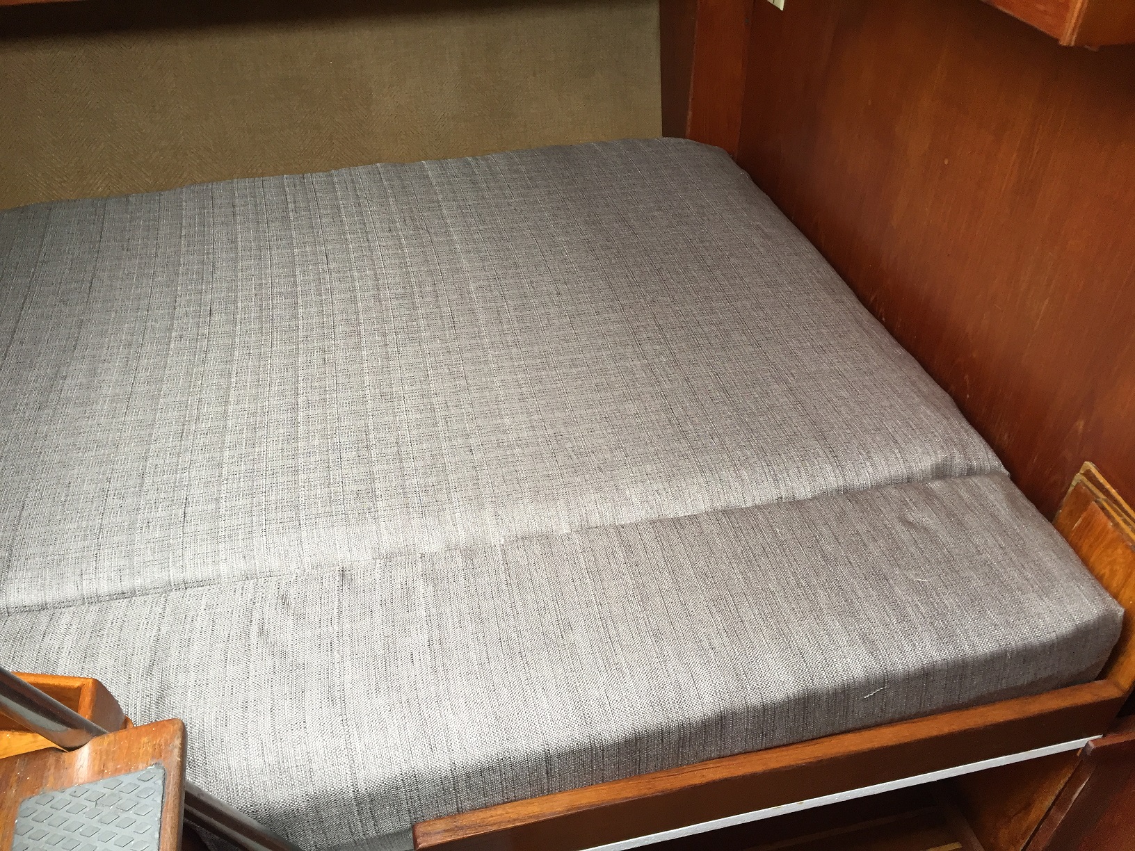
The link to a topper shows a V-berth. That was our daughter’s cabin until very recently. She’s on her own now and rarely joins us on the boat anymore. Maybe when we hopefully have grandkids the bunk will get used again. For the first time, we slept up there last summer when we had guests onboard. We found it almost impossible to get in and out of there. You have to do a somersault to get in and out. Our V-berth mattress is one piece so there’s no crack to fall into. It’s comfortable once you get in there but a PIA to do so. Here’s a link to the mattresses we bought. Easy to cut with an electric knife.
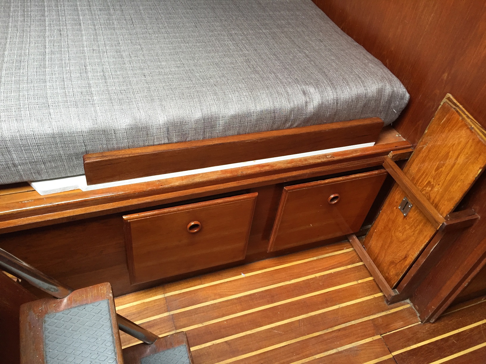
https://www.amazon.com/gp/product/B01N7R9IHA/ref=oh_aui_search_asin_title?ie=UTF8&psc=1I added a photo that shows aft. This is taken without the filler in place. You can see the lip the shelf sits on. The bunk is exactly as wide as it used to be with the addition of a filler, approx 12″. The aft end doesn’t get wider. The fiddle holds the two pieces together. I’ll be cutting a mattress pad to fit too. If I’m covering the thing with a mattress pad, sewing a cover on the mattress was probably a waste of time.
I want to be able to remove the filler when not in use, otherwise the aft cabin would be very narrow. I widened the nav station many years ago; got tired of banging my head against the breaker-panel.
The mattress is quite comfortable. It’s much thicker than the original mattress provided by the builder and raises the bunk as expected. This reduces the clearance to the bookcase. Adding yet a mattress topper might make it difficult to read in bed.
Attachments:

IMG_0955.jpg
RichCarterParticipantI had trouble loading photos, had to do them one at a time with reduced resolution.
Next project is to refinish the woodwork in the aft cabin, for the Nth time.
BTW: I made the cushion covers myself. I’m not ready to quit my day job with my sewing projects but it came out OK. I bought a Sailrite sewing machine and that made the job much easier. That thing will sew through a sheet of plywood if you can get it under the foot.
Attachments:
IMG_0957.jpg
RichCarterParticipantshelf stowed
Attachments:

IMG_0959.jpg
RichCarterParticipantphotos
Attachments:

IMG_0961.jpg
RichCarterParticipantI removed mine years ago. As I recall, there’s a hydraulic line that goes to an oil pressure fitting on the engine. When the engine is running and builds up oil pressure, it pushes a slave cylinder on the brake to disengage the brake caliper. The brake disc goes on the transmission output coupler and the caliper mounts to the transmission face. Maybe someone else has photos of the installation to share.
Pads wear and may need replacement. There’s a thread elsewhere on this site with info on ordering replacement pads.
Rich
RichCarterParticipantI’m in the process of replacing the mainsail boom on my 424. A friend gave me a boom from his Vagabond 47. He re-rigged his wooden spars with an aluminum set of spars from US Spars. They incorrectly shipped him a short boom and reshipped one of the correct length. They left him with the first boom, too short for his rig and just about right for mine. This has fittings for up to four internal lines. Their website parts manual shows the parts and rigging method for a single-line reef. The rigging assumes that you’ll run all your lines back to the cockpit, including the halyard winch. You could put a turning block at the base of the mast to redirect the reef line to a mast mounted winch but you’ll lose all advantage. I decided to leave the reef lines external and ordered external blocks and track from Garehauer.
For coastal cruising, I don’t reef. Reefing is for pussies. If the wind picks up I ease off the main. With full battens, I can depower the main without flogging it to death. This works up to about 40kts apparent. More than that and I stay in port. Now if I were headed offshore, I’d certainly want reef points, meow…
The US Spars system is expensive. Even though I got a free boom, I ended up buying some parts to replace what was missing, goosneck, reef bail and block, outhaul tackle, etc. So far, I’m in to it for about $700. I don’t know what the boom would have cost but I would guess it’s close to a grand alone.
So why am I replacing my boom? The outhaul on the 424 is junk. I didn’t expect these odd parts to be so expensive or I may have fixed what was there. The US Spars boom is very nicely made so it’s not wasted money.
Rich
1 user thanked author for this post.
RichCarterParticipantMy boat, and I think all 424s, was built with a mechanical fuel gauge. This was, IMHO, a cheap solution. I had to kneel down with a flash-light to view the gauge. Not practical when filling the tank and not something I enjoyed doing under any circumstances. When I repowered, I replaced my tank and had the tank company install an electric sender. They of course cut the tank holes to match their sender. I don’t suggest reinstalling a mechanical sender.
No matter which sender you install, beware of the position the sender is installed in. There’s a baffle in the tank. If you install it improperly, the sender arm will hit the baffle and not register properly. You can get a sender that doesn’t have an arm. Instead, it travels on a pair of vertical rails. You must get the sender length correct for this to work but it avoids the problem of hitting the baffles. That’s what I had done. I think the rail length can be shortened by cutting it.
If it were me, I’d toss the mechanical gauge you bought and put in an electric one.
If you chose to install the mechanical sensor you bought, I’d recommend drilling the sender holes to mach what you have. Rotate it so the gauge arm doesn’t hit the baffle.Rich
RichCarterParticipantIt looks like a picture of a dog to me.
RichCarterParticipantWhich engine do you have? In general, there are four sensors on your engine two each for oil and temperature. Each pair consists of a sensor that connects to the engine instrument and a switch that connects to the alarm. For oil, the alarm switch on the engine is a generic part sold in almost any automotive store. I looks like a spark-plug with a small wire on the top instead of a heavy spark-plug wire. It grounds the terminal on the top of the switch when oil pressure is low. That wire goes to the alarm and joins with the high temperature alarm switch. The other end of the alarm buzzer or bell goes to the ignition switch. Having the alarm sound when the key is first turned on is typical behavior. As I recall, Westerbeke had a fuel-pressure switch in addition to the other two already mentioned. Power to the alarm went through this switch so the buzzer wouldn’t sound when the engine is first turned on. I didn’t bother with this because I think it’s a mistake to mute the buzzer on startup. Hearing the buzzer on startup is an indication that the alarm system is functional. If you want the buzzer muted during the glow-plug warm-up, check the fuel-pressure switch. It should be on the side of your fuel pump. It would have two terminals on it. One would go to the instrument panel ignition power. The other would go to your alarm buzzer or bell.
-
AuthorPosts